Wednesday, November 28, 2012

NFB ( NO FUSE BREAKER )


http://electricisa.blogspot.com/2012/11/nfb-no-fuse-breaker.html
NFB (no fuse breaker) is one component of the electrical safety overload and short circuit. then what's the difference with the MCB?
be patient, we will discuss shortly.
the  function can be seen from the above definition of the meaning of that is, as a means to disconnect ( break ) electrical current when the load handled by the these tools becomes overload or short circuit, or the current through it exceeds that limit has been set at the NFB.

difference between the NFB with MCB is the limit value of current that can be served by both ini.MCB tool used for smaller load is typically modest and still can not diubah.sedangkan NFB has a larger current limit and used to secure his load currents more large and in some types of NFB anyone can set its current limit, of course, the greater the value of the current limit higher price NFB
HOW NFB WORKS 
Under normal circumstances:
after the tool is set current limit permitted. pull the lever to the OFF position and Rev to the ON position, so that an electrical current can flow and supply expenses.
overcurrent / overload / shortcircuit conditions:
electric current that flows through the tool and exceed the specified limits, then the metal bimetallic temperature inside will rise and the curved or bent, so that the contacts will be disconnected and the lever will go to the center position or TRIP. to restore it to its original state should be scaled first lever to the OFF position and then raised to the ON position. of course after checking the load and circuit underneath
HOW TO INSTALL NFB
before we put the NFB we have to count the total electric current  flow on this tools. to calculate the amount of current we can look at the name plate of a load (motor pump) and summing the the amount. then we determine the diameter of the cable conductor cross-sectional area accordingly. then we select the amount of NFB that will be used,
installation of equipment is series assembled on the top of  circuit and before the motor (load).


Tuesday, November 27, 2012

MCB ( MINIATUR CIRCUIT BREAKER )

ELECTRICISA.BLOGSPOT.COM MCB
MCB ( MINIATUR CIRCUIT BREAKER)  is an electrical device that is designed in such a way as to secure an electricity network from harm overload and short circuit.
FUNCTION MCB:

MCB serves to cut off power automatically if the power is delivered exceeds the limit value. This MCB is on / off, and can also serve as the main switch in the house. If the MCB is in a state bargainser off, then all the power in the house was halted. The switch is normally turned off when the repairs will be carried out electrical installations in the home.

MCB is a safety net that works on the principle of Bimetal, with some elements of the operation are:
1. Terminal trip (Bimetal)
2. Electromagnetic trip (coil)
3. Arc extinguishing
4. mechanisms of termination
By construction, the MCB has two ways of termination, namely: termination by heat and by electromagnetic.
1. Termination by the heat carried by the bimetallic rods, which are: combination of two different metals expansion coefficient of metal. If there is more flow due to overload, the bimetal will bend due to the heat and will push the breaker lever to release the mechanical lock. This causes the MCB trip.
2. Termination by ektromagnetik performed by the coil, if a short circuit occurs then the coil will be induced and the surrounding area there is a magnetic field that will pull the lever shaft and operate the breaker. To avoid the effects of melting, the high heat sparks that can occur when the termination will be muted by extinguishing arc (arc-shute) and sparks that arise will go through the blades of the arc-shute.
An automatic safety advantage is that it can be used again immediately after the termination, the automatic safety clutch freeway because there is otomatic clutch can not be used again if problem not improved.
The nature of the MCB are:
a. Load current can be considered when the heat generated heat in excess of permitted
b. Short circuit current can be decided without any slowdown
c. After the repair, the MCB can be reused.

The workings of MCB
1. Based on the heat. At MCB are bimetal plate (mix two different metals heat expansion coefficient). Bimetal will fold if there is excessive heat through. Bimetallic plates are curved because the heat will move the lever and the breaker will disconnect electric current.
2. Based on electromagnetic. Termination of electric current carried by the coil method is contained in the MCB. In the event of excessive current (MCB limit) will be induced so that the coil generates a magnetic field that will pull the lever breaker, so contact the MCB will be disconnected.

The size of the ability to decide MCB electrical current depends on the specifics of each MCB. For example, for a capacity of 2A MCB MCB will then work cut electric current when an electric current through the MCB exceed 2A. Each installation must take full account of the power requirements of each installation is installed.
It should be noted also for use in power installations that use the 3 phase occurs when the MCB trip (interference), the third MCB connected to each phase (RST) to open / end together.


Monday, November 26, 2012

DIRECT CURRENT ELECTRICAL MOTOR

http://electricisa.blogspot.com/direct current electrical motor
direct current electrical motor  DC motors / direct current, as the name implies, uses a direct current indirect / direct-unidirectional. DC motors are used in special applications where high torque ignition or acceleration over a broad speed range.this is another article about electric motor while we have discuss alternating current electrical motor.
Figure 3 shows a DC motor which has three main components:
• Pole field. Simply put, the interaction of the two magnetic poles will cause the rotation of a DC motor. DC motor has a stationary field poles and armature that moves in the space between the poles bearing field. A simple DC motor has two field poles: north and south poles. The magnetic lines of force extend across the opening between the poles from north to south. For motors larger or more complex consists of one or more electromagnets. Electromagnetic receive electricity from an outside power source as the field structure.
• Dinamo. If the current goes through the armature, it will become an electromagnet. Cylindrical dynamo, connected to the countershaft to drive the load. For the case of a small DC motor, the armature rotates in a magnetic field formed by the poles, to the north and south magnetic poles change locations. If this happens, the current is reversed to switch poles north and south dynamo.
• commutator. This component is mainly found in DC motors. Its purpose is to reverse the direction of the electric current in the armature. commutator also helps in the transmission of current between the armature and resources.
The main advantage is the speed of DC motor is easy to control and does not affect the quality of power supply. DC motors can be controlled by adjusting:
• armature voltage - increasing the armature voltage will increase the speed.
• Flow field - reducing the field current will increase the speed.

DC motors are available in many sizes, but their use is generally limited to a few low speed, low to moderate power usage, such as machine tools and rolling mills because of problems with mechanical commutation at a larger size. Also, they are restricted for use only in areas that are clean and not dangerous because the risk of sparking at the brushes. DC motors are also relatively expensive compared to AC motors.

The relationship between speed, field flux and armature voltage is shown in the following equation:

Electromagnetic force: E = KΦN

Torque: T = KΦIa

Where:
E = electromagnetic force developed in the armature terminals (volts)
Φ = flux field is directly proportional to the field current
N = speed in RPM (revolutions per minute)
T = torque electromagnetic
Ia = armature current
K = constant equation

DC Motor Types / Unidirectional Flow

a. Separate power DC motor / Separately Excited, If the field current is supplied from a separate source, it is called a separate power source DC motor / separately excited.

b. DC motors own resources / Self Excited: shunt motor. In a shunt motor, the field winding (shunt field) is connected in parallel with the armature winding (A). Therefore the total line current is the sum of the field current and armature current.

Here's about the speed of a shunt motor (ETE, 1997):
• Speed ​​is not constant in practice depends on the load (up to a certain torque as speed decreases, see Figure 4) and is therefore suitable for commercial use with a low initial load, such as machine tools.
• Speed ​​can be controlled by inserting resistance in series with the armature arrangement (reduced rate) or by inserting resistance in the field current (increasing speed).

c. Own power DC motors: motor series. In a series motor, the field winding (shunt field) connected in series with the armature winding (A). Therefore, the same field current to the armature current.

Here's about the speed of the motor series (Rodwell International Corporation, 1997; LM Photonics Ltd, 2002):
• Speed ​​is limited to 5000 RPM.
• It must be avoided running series motor with no load because the motor will accelerate.
Series motors are suitable for applications that require high starting torque, such as cranes and hoists.
d. Motor DC Compound / Combined.
DC compound motor is a combination of series and shunt motors. In this motor, the field winding (shunt field) connected in parallel and in series with the armature winding (A) as shown in Figure 6. Thus, the motor has a starting torque nice and steady pace. The higher the percentage of incorporation (ie, percentage of field windings are connected in series), the higher starting torque that can be handled by this motor. For example, the incorporation of 40-50% makes the motor suitable for hoists and cranes, motors standard compound (12%) do not match
fuft..thats LOL all article about electric is make me addict but its fun to share with all readers,thanks 

ALTERNATING CURRENT ELECTRICAL MOTOR

http://electricisa.blogspot.com/alternating current electric motor
alternating current electric motor  using an electric current that reverses direction at regular intervals. AC electric motor has two basic electrical parts: a "stator" and "rotor"

The stator is the stationary electrical component. The rotor is the rotating electrical component rotates the motor shaft. The main advantage of DC motors over AC is that the speed of an AC motor is more difficult to control. To overcome this disadvantage, AC motors can be equipped with a variable frequency drive to increase control while reducing its speed. Motor is an induction motor is the most popular in the industry because of its reliability and easier maintenance. AC induction motors are inexpensive (half or less than the price of a DC motor) and also provide power to weight ratio is quite high (about twice a DC motor).

Types of Motor AC / Alternating Flow-Back

a. Synchronous motor. Synchronous motor is an AC motor that works at a fixed speed frequency of the system. These motors require direct current (DC) for power generation and has a low starting torque, and therefore synchronous motor is suitable for applications that start with low loads, such as air compressors, motors and generators frequency changes. Synchronous motors are able to improve the power factor of the system, so it is often used in systems that use a lot of electricity.

The main components of a synchronous motor is
• Rotor. The main difference between synchronous motor with an induction motor is that the rotor synchronous machines running at the same speed as the rotation of the magnetic field. This is possible because the magnetic field of the rotor is no longer induced. The rotor has permanent magnets or DC-excited, which was forced to lock in a certain position when confronted with another magnetic field.
• Stator. The stator produces a rotating magnetic field which is proportional to the frequency supplied.

This motor rotates at synchronous speed, which is given by the following equation (Parekh, 2003):

Ns = 120 f / P

Where:
f = frequency of the supply frequency
P = number of poles

b. Induction motor. Induction motors are the most common motors used in various industrial equipment. Its popularity is due to the design, which is simple, inexpensive and easily available, and can be directly connected to an AC power source.

Component of induction motor has two main electrical components:
• Rotor. Induction motors use two types of rotor:
- Squirrel cage rotor consists of a thick conductor rods are embedded in parallel slots plots. These bars are short-circuited at both ends by means of short-circuiting rings.
- A wound rotor has three-phase windings, double layer and distributed. Many poles as the stator. Three phases digulungi wire on the inside and the other end connected to a small ring attached to the stem as a brush attached to it.
• Stator. The stator is made of a number of stampings with slots to carry three-phase windings. It is wound for number of poles. The rolls were spaced at 120 degrees geometry.

Classification of induction motor

Induction motors can be classified into two main groups (Parekh, 2003):
• Single-phase induction motor. This motor has only one stator winding, operates with single-phase power supply, has a squirrel cage rotor, and require a tool to turn the bike. So far this bike is the most common type of motor used in home appliances, such as fans, washing machine and clothes dryer, and for the use of up to 3 to 4 Hp.
• three-phase induction motors. Rotating magnetic field produced by a balanced three-phase supply. These motors have high power capabilities, can have a squirrel cage or wound rotor (although 90% had a squirrel cage rotor), and the ignition itself. It is estimated that about 70% of the motor industry uses this type, for example, pumps, compressors, conveyor belts, power lines, and a grinder. Available in sizes 1/3 to hundreds of horsepower.

Induction motor speed

Induction motor works as follows: Electricity is supplied to the stator, which produces a magnetic field. This magnetic field moves around the rotor at synchronous speed. Rotor currents produce secondary magnetic field, which is trying to fight the stator magnetic field, which causes the rotor to rotate. However, in practice, the motor never runs at synchronous speed but the "base rate" is lower. The difference between the two speeds is the "slip / slide" that increases with increasing load. Slip only occurs in an induction motor. To avoid slip ring can be fitted a sliding / slip ring, and the motor is called "motor slip ring / slip ring motor".

The following equation can be used to calculate the percentage of slip / slide (Parekh, 2003):

% Slip = (Ns - Nb) / Ns x 100

Where:
Ns = synchronous speed in RPM
Nb = base speed in RPM

The relationship between load, speed and torque
 graph torque vs. speed three-phase AC induction motor with the current set. When the motor (Parekh, 2003):
• Start turns lights are flame high initial currents and low torque ("pull-up torque").
• Achieve 80% of full speed, the torque is at the highest level ("pull-out torque") and the current begins to drop.
• At full speed, or synchronous speed, torque and stator currents down to zero.
also read article about direct current electrical motor

ELECTRIC MOTOR


http://electricisa.blogspot.com/electric-motor
electric motor is an electromagnetic device that converts electrical energy into mechanical energy. This mechanical energy is used for, for example, rotating impeller pump, fan or blower, driving a compressor, lifting materials, etc. in the industry and is also used in household electrical appliances (such as mixers, electric drill, fans).

Mechanism of action for all types of electric motors are generally the same:
• An electric current in a magnetic field will experience a force.
• If the current carrying wire is bent into a circle / loop, then both sides of the loop, ie at right angles to the magnetic field, will get a force in the opposite direction.
• pair of forces creates playlists / torque to rotate the spindle.
• These motors have multiple loops on dynamo to provide a more uniform torque and magnetic field generated by the coil arrangement called the electromagnetic field.

In understanding an electric motor, it is important to understand what is meant by the motor load. Load refers to the rotary power output / torque in accordance with the required speed. Expenses generally be categorized into three groups:
• constant torque load, is the load which the output power varies with the speed of operation, but the torque does not vary. Examples of constant torque loads are conveyors, rotary kilns, and constant displacement pump.
• Load with variable torque, is the torque load that varies with the speed of operation. Examples of variable torque loads are centrifugal pumps and fans (torque varies as the square of the speed).
• Constant power load, a load torque change with demand and inversely proportional to the speed. An example for a constant power load tools are machines.

ELECTRIC MOTOR can be divided into two groups based on the use of electric current. the direct current electric motor and alternating current electric motors


ELECTRIC CONDUCTOR

http://electricisa.blogspot.com/electrical conductor

electric conductor  is a  liquid / solid / gas material that can conduct electricity easily.Good conductor is one that has a smaller resistivity. In general, the metal is conductive. Gold, silver, copper, aluminum, zinc, iron successive having resistivity greater. So as gold is a very good conductor, but because it is very expensive, the economic copper and aluminum are the most widely used.
Definition conductor or conductor understanding. Conductor or conductor is a substance or material which is able to deliver energy, both electrical energy and heat energy, either solid, liquid or gas. The materials that are conductors is normally used to make tools that are needed energy transfer, such as pans, irons, cable and solder.
1.1 Type Conductor Materials
The materials used for conductors must meet the following requirements:
1. Conductivity is quite good.
2. Mechanical strength (tensile strength) is quite high.
3. Length expansion coefficient is small.
4. Elastic modulus (modulus of elasticity) is quite large.
The materials used as conductors, among others:
1. Common metals, such as copper, aluminum, iron, and so on.
2. Alloy (alloy), which is a metal of copper or aluminum that were mixed in a certain amount of other types of metal, which is useful to increase mechanical strength.
3. Metal alloys (composite), ie two or more metals are combined by means of compression, fusion (smelting) or welding (welding).

1.2 Classification of conductors
1.2.1 Classification of conductors according to the material:
1. ordinary metal wire, for example:
a. BBC (Bare Copper Conductor).
b. AAC (All Aluminum Alloy Conductor).
2. wire alloys (Alloy), for example:
a. AAAC (All Aluminum Alloy Conductor)
b. alloy wire (composite), such as: copper coated steel wire (Copper Clad Steel) and steel wire coated aluminum (Aluminum Clad Steel).
3. wire wrap mixture, ie the wire windings consist of two or more metals,
example: ASCR (Aluminum Cable Steel Reinforced).

1.2.2 Classification of conductors by construction:
1. solid wire (solid wire) Berpenampang round.
2. berlilit wire (standard wire) comprising 7 to 61 solid wire, wound into one, usually layered and concentric.
3. hollow wire (hollow conductor) is a hollow wire is set to get a huge line outside the center.

1.2.3. Classification of conductors according to its physical form:
1. bare conductors.
2. insulated conductor, a conductor on the outside naked and isolated in accordance with the allotment of work stress, for example:
a. Twisted wires.
b. Cable NYY
c. Cable NYCY
d. Cable NYFGBY

1.3 Characteristics Conductor
There are 2 (two) types of conductor characteristics, namely:
1. mechanical characteristics, which indicate the physical state of the conductor which states the tensile strength of the conductor (from SPLN 41-8:1981, for 70 mm  sheathed conductors AAAC-S at a temperature of about 30  C, the maximum capacity of the conductor is to deliver current 275 A).
2. electrical characteristics, which shows the ability of the conductor to the electric current passing through it (from SPLN 41-10: 1991, to 70 mm2 sheathed conductors AAAC-S at a temperature of about 30o C, the maximum capacity of the conductor to deliver current is 275 A).

1.3.1 Electrical Conductivity
Electrical conductivity properties of the material represented by the conductivity, which is the inverse of resistivity or resistivity conductor, where the conductor resistivity is defined as:
R. A
ρ = ----------
l
where;
A: cross-sectional area (m2)
l: length of conductor (m)
Ώ: Conductor resistivity (ohm.m)
R: Conductor resistance (ohms)
ρ: conductivity

1
a = ------
ρ

Stating ease - ease of a material to carry electrical current. Unit of conductivity is (ohm meter). Conductivity is the electrical properties required in various applications as a conductor of electricity and has a very wide price range. Metals or materials that are good electrical conductor, electrical conductivity of the order of 107 (ohm.meter) -1 and vice versa insulator material has a very low conductivity, which is between 10-10 up to 10-20 (ohm.m) -1 . Between these two extreme properties, there is a semi-conductor material conductivity ranging from 10-6 to 10-4 (ohm.m) -1. In contrast to the low voltage cables, medium voltage cables for the fulfillment of the function of the conductor and the safety of the use of, or the third type conductivity properties used above all.

-------------------------------------------------- ----------------------------------------
The electrical conductivity of metals ohm meter
Silver (Ag) ............................ 6.8 x 10⁷
Copper (Cu) ....................... 6.0 x 10⁷
Gold (Au) .......................... .. 4.3 x 10⁷
Aluminum (Ac) ................... .. 3.8 x 10⁷
Brass (70% Cu - 30% Zn) ... 1.6 x 10⁷
Iron (Fe) .............................. 1.0 x 10⁷
Carbon steel (FFE - C) ............. 0.6 x 10⁷
Stainless steel (FFE - Cr) ...... 0.2 x 10⁷

Table 1. Electrical conductivity of various metals and alloys At Room Temperature.

1.3.2 Criteria for quality conductor
Conductive metallic conductivity is strongly influenced by the elements - alloying elements, major impurity or crystal imperfections in the metal, which is the third of a role in the process of manufacture of the conductor itself. Element - the element of the tour besides affecting the electrical conductivity, it will affect the properties - mechanical and other physical properties. Pure metal has better electrical conductivity than the lower purity. However, the mechanical strength of pure metal is low.
Conductor of electricity, in addition to requiring high conductivity also requires certain physical and mechanical properties that are tailored to the use of the conductor itself.

In addition to technical problems, the use of metal as a conductor was also largely determined by the economic value of the metal community. Thus a compromise between technical and economic value of metal to be used absolute attention. Termurahlah compromise value that will determine which metal will be used. At this time, Metal Copper and Aluminum is a metal that was selected among other types of metal conductors that meet the technical compromises cheapest economical.

Of the types of metal conductors in Table 1. above, copper is a conductor of the longest used in the field of electricity. In 1913, by the International Electrochemical Commission (IEC) set a standard that indicates conductivity copper wire which was then known as the International Annealed Copper Standard (IACS). The standard states that for copper wire that has been softened by annealing process (annealing), has a length of 1m and 1mm2 cross sectional area, and have the electrical resistivity (resistance) is not more than 0.017241 ohms at a temperature of 20oC, has declared 100% IACS electrical conductivity.

However, with technological advances making process copper achieved, where the level of purity copper conductor wire is much higher than in 1913, the electrical conductivity of copper wire today can reach above 100% IACS.
For Aluminium wire, regular electrical conductivity compared to the standard copper wire. According to standard ASTM B 609 for aluminum wire of the type EC grade or AA series 1350 (*), electrical conductivity ranged from 61.0 - 61.8% IACS, depending on the hardness or temper. As for the conductor wire of aluminum alloy AA 6201 series, according to standard ASTM B 3988 persaratan electrical conductivity can not be less than 52.5% IACS. 6201 Conductor Wire is usually used for the type of cable materials All Aluminium Alloy Conductor (AAAC).

In addition to the requirements of the electrical properties such as electrical conductivity above, other quality criteria must also be met include all or part of nature - the nature or conditions of the following, namely:
a. chemical composition.
b. tensile properties such as tensile strength (tensile strength) and tensile strain (elongation).
c. bending properties.
d. diameter and the allowable variation.
e. surface condition of the wire must be free from defects, and others.
ELECTRICAL PANEL

http://electricisa.blogspot.com- electric panel
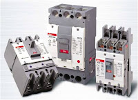
electrical panel is a panel or rack in which there are several electrical components that regulate a network or electrical circuit.

function electrical panel
electrical panel or terminal serves as a network / electrical system that can easily be controlled by humans and capable of displaying accurate information about power lines or electrical circuits handled
requirements of electrical panels
electrical panel must have a standard system of rules that must be met in order for an electrical panel function optimally and reserve the risk is small, and easily display the information of a circuit or power lines are handled by electrical panel
http://electricisa.blogspot.com- electric panel

electrical panel components
electrical panel components broadly categorized as follows:
1. body panel: made ​​of material stronger and stronger to accommodate some electrical components are handled, (iron, aluminum, plastick etc.)
2. rail or terminal: to place electrical components
3. panel: protect electrical components are handled in order to avoid interference from outside
4. information viewer components: a component that can display information such as the user needs voltmeters, ammeters, frequency meter, the indicator light.
5. conductor of electric current: wire or conductor to connect several components inside
6. Insulation: insulate some conductors to prevent short circuits or electric shock
7. component control or switch: to regulate the network or electrical circuit
8. electrical components: electrical safety components, (fuse, MCB, NFB, etc..)


http://electricisa.blogspot.com- electric paneltypes of electrical panels:
electrical panel is divided into several types including:
electrical distribution panel
The main electrical panel
control panel circuit
electrical safety panel
electrical system indicator panel
capacitor bank panel
generator synchronization panel
etc.


ELECTRIC CIRCUIT

http://electricisa.blogspot.com/electric-circuit

electrical circuit is an arrangement or electrical system typically consists of several components
(power source - electricity load - conductor of electricity - electrical controller etc..)
made ​​in such a way as to obtain a specific purpose, usually to ease a job, for example, illuminate a room, raise water from wells, etc.


power source is obtained from various sources such as batteries, battery, and generator
electrical load can be coils, electric motors, lighting, etc..
electrically conductive form of wire / cable conductor
electrical controller can be either electrical switches, sensors, and coil contactor.


general electric circuit is divided into 3 types of electrical circuits there are:
1. series circuit:
which is composed of a series in series in which the absence of branching flows in a closed circuit
2. parallel circuit:
which is composed of a series of branching Paralell are are current in a closed circuit
3. combinations circuit :
a circuit that combines a series circuit and closed circuit  Paralell circuit.

closed circuit is an electrical current can flow through a conductor and a load of positive pole toward the negative pole without interruption.
open circuit is a circuit where the electrical current from the positive pole is not toward the negative pole
remember to read our another articles about electric


DIRECT CURRENT

direct current.electricisa.blogspot.com
direct current  ( DC ) is an electric current which have constant or periodic fixed value in time periodic, just take a look the picture from 0 time untill 2 second the value is still on 0.5.there is no frequency and amplitude.different from the alternating current which has a frequency and amplitude.
direct current frequently encountered in home appliances and telecommunications devices. such as mobile phones, dvd player, etc.direct current source can we get from batteries, batteries, solar cells, etc.other than from the sources we can change alternating current into direct current using an adapter containing components rectifier to get direct current.

direct current widely used in our lives because it is safe and easy process and circuit assembly. just look at the motorcycle electrical system or our cars, electric current direction is obtained from the accumulator is filled by an alternating current generator are rectified and stored in the battery, a fully charged battery will supply some of the needs of the motorcycle electrical systems as well as our cars, such as lighting lamps, bell horn, to regulate the engine ignition system.

actual direct current is also dangerous to humans, remember in my previous article about the electric shock. either direct current or alternating current can cause negative effects to humans exposed to electric shock.


Thursday, November 22, 2012

ALTERNATING CURRENT

electric is a-alternating current
definition of alternating current
alternating current is an electric current voltage fluctuations within a certain time, from positi value to 0 and then to negative and back to positive values​​, the cycle continues over a certain time. so that alternating current has a frequency and amplitude,this is because the source generator is also a change of the magnetic poles in the process of formation of electrical energy.alternating currents encountered in many electrical systems, such as the power grid in the home, in the office, on the road, and others we can find alternating current on tv, water pumps, and others.

we suppose that an alternating current having a frequency 60hertz this means in a second cycle is repeated flow of 60 times, we can measure alternating current and see the waves in the tool called an oscilloscope, this device we can calculate the wavelength, amplitude, frequency , etc
there are al  lot of


there are many calculations that rely wave alternating current.
from here we can calculate the power loss, the value of the voltage, wavelength, amplitude, and therefore the subsequent discussion we will further discuss the things that are related to electricity


TRANSFORMATOR

transformator  is an electrical device or component that serves to change the amount of voltage


The use of transformers
Transformer (transformer) used in electrical equipment, especially that require changes or adjustments magnitude of alternating voltage. Eg radio requires 12 volts when the voltage of electricity 220 volts, it would require a transformer to convert alternating voltage to 220 volts alternating voltage of 12 volts. Examples of power tools that require a transformer are: TV, computers, copy machines, electrical substations, and so on.


Working Principle of Transformer
The working principle of a transformer is when the primary coil (main) is connected with a source of alternating voltage, electric current changes in the primary coil cause a changing magnetic field. Changing magnetic field amplified by the presence of an iron core and iron core is delivered to the secondary coil, so that the ends of the secondary coil induced emf will arise. This effect is called mutual inductance (mutual inductance).

Component transformer 
Transformer (transformer) is a device used to raise or lower the voltage of alternating (AC). The transformer consists of three basic components, namely: first coil (primary) which acts as the input, the second coil (secondary) which acts as the output, and the iron core that serves to amplify the magnetic field is generated.

Transformator types

Types of transformers varies, among which are a step up, step down, autotransformator and 3-phase transformers. 3-phase transformer is: three transformers are connected to each other specifically. Primary winding is usually connected in star (Y) and the secondary windings are connected in delta (Δ).

Most of the power transformer has a core coils immersed in transformer oil, transformer-especially in large capacity power transformers. because it has the properties of transformer oil as the heat transfer medium and also serves as insulation anyway (having high breakdown voltage power) that serves as a cooling and insulating medium.

Thus a brief explanation of transformer function, hopefully you can understand the working principle of transformer and transformer types.


ELECTRIC


electric,electrical,electricity

ELECTRIC or ELECTRICITY is the most important energy in the universe, everyone is almost certainly dependent on electricity.
we find a lot of electrical energy in their daily lives, ranging from light to advanced technology, all of these require electricity. there are those among us who already know the definition and understanding of electricity, but many do not know. just imagine how our lives without electricity ..? for sure we will have difficulty in performing daily activities


electric,or electricity is an energy, energy that an object or substance due to differences in the charge of the object. an object tends to negatively charged if the amount of negative charge more than the positive charge. vice versa an object tends to positively charged if the amount of negative charge much less than the amount of positive charge. whereas an object or substance tend to be neutral if the amount of negative charge equal to the amount of positive charge. negative charge can move on from one object to another object whereas positive charges tend to be quiet passive.  negative charge displacement caused by several factors such as impact, heat, and others.Another name of the negative charge is electron, positive charge is  proton.
 electric or electricity energy can not be created and can not be destroyed, but the electrical energy can be transformed from one form of energy into another form of energy. This is the law of conservation of energy. The first thing we will discuss is the energy when electricity was discovered. electricity actually been around since the earth and the universe formed, it can be seen in the event of thunder. thunder is an example of electrical energy that existed before humans explored electrical energy.and also there are some animals that have electricity like an electric eel.
electric or electricity is a very broad science to discover, therefore, we should start from the easy and simple things first and then proceed to the more complex case, from here we've got an idea of ​​the definition of electricity and how electricity is formed. would but still very far to understand and learn the power. patience and perseverance is the key to mastering the full electric. Do not forget to read the other articles in this blog to increase your knowledge about electricity


ELECTRIC SHOCK

electric shock-http://electricisa.blogspot.com

electric shock is an event where someone electrocuted, while an electric current can flow in a closed circuit, it means a person is electrified and the body is regarded as a conductor of electricity, this are the simply example: someone who has touched the wire conductor of electric current phase while the another body touching neutral or earth grounding, allowing an electric current to flow into the body of someone, and this is called an electric shock

electric shock usually occurs in alternating current electricity, because the human body is not able to withstand the electric current, whereas the human resistance will vary between one and the other, there is a strong electric shock to a certain voltage others fainting or even death in when a certain voltage electric shock. average human can withstand alternating electrical current with a voltage range from 0 to 10 volts. over voltage that then someone usually faint or even die.

electric shock actually occurs in electric with direct current and is also dangerous to humans, then actually what causes electric shock dangerous for someone? turns an electric shock can be harmful to humans based on several things and factors, including the magnitude of the voltage, the amount of electric current, and frequency and duration of the time when someone is electrocuted, apart from a few things mentioned above are also influenced by the shock resistance of the human body itself. it depends on a person's body resistance during electric shock.

electric shock causes electrified body will react depending on the type of electric shock, an electric current flowing in the body, resulting in impaired heart rate disruption of blood flow in the body and cause the muscles to spasm. the greater the current, voltage, power and frequency the longer it lasts cause death to a person who gets an electric shock.

electric shock can be anticipated and prevented with a few things. including isolating all current-carrying conductor of electricity, install ELCB (Earth leackage Circuit Breaker) is an electrical device that functions to prevent a shock hazard to humans or the workpiece, the tool is mounted on the upper circuit, to know more about how to install this tool please visit our other articles on this blog.
we already know the overall electric shock, electric shock hazards, how to prevent electric shock, from the article above. hopefully with increasing our knowledge of electricity will increase our vigilance and use of electrical energy as well, and remember beware of electric shock.


VOLTAGE

voltage
voltage is  potential difference is the amount of a charge with other charges and units called volts ( v ) , the voltage can be simply described by a strong flow of waterpower voltage is rushing water, the greater the force pushing the water, the greater the energy to move something, so does the voltage, the greater the voltage, the greater the power generated to supply the equipment.

 voltage in physics can be described by the potential energy contained in a substance to other substances. this was due to differences in the amount of negative charge and positive charge amount contained in a substance. suppose a substance (a substance we call A) has a number of negative charge and positive charge 10 pieces 30 pieces the substances they lack the negative charge as much as 20 pieces, therefore they have the potential energy of 20 pieces and that means the voltage of an object against the object the other is -20 pieces, but depending on the substance to be paired, if the substance partner (we call substance B) has an energy shortage -10 or negative charge 10 pieces of the voltage or potential difference of objects a and B is (-20) plus (-10) then the result (-10) but within the science of electricity is not as easy as a matter of the above there are several factors for the in put. maybe next time we will discuss.

voltage in an electrical distribution network can be categorized into low voltage - high voltage - high voltage, masing2 have a certain amount of restriction in any groups. in some countries the standard voltages to the end customer and the 110 volt range for 1-phase 220 ​​volts and 380-400 volts for 3 fasa.dan these included low voltage. while to raise the voltage and lower voltage used a device called a voltage transformer, step-up transformer to raise the voltage, whereas for reduce the voltage devices called step-up transformer.
voltage transformer can only work on alternating electrical current.


tool used to measure the voltage such voltmeter, oscilloscope, and others. measurement circuit coupled parallel with the voltage to be measured
The following are a few tables voltage calculation:

· 1 Mega volt (Mv) = 1,000,000 volts

· 1 Kilo volt (Kv) = 1.000 volts

· 1 Mili volts (mV) = 0.001 volts


- P      =  V x I 
- V     =   ( I x I ) x  R

*    P : Power (W)
*    V : Voltage (V)
*     I  : current (A)
*     R : Resinstance ( Ohm ) 

ELECTRIC CURRENT

electric current - http://electricisa.blogspot.com

Electric current is the large number of electrical charge resulting from the movement of the electrons are negatively charged, flowing through a point in an electric circuit per unit time. An electric current can be measured in units of Coulomb / second or amperes. electrical current can be clasified to a direct electric current and alternating electric current.

direct electric current is the amount of electric current The set voltage in a fixed or unchanging. This means that the direction of the electric current has a frequency 0. direct electric current frequently encountered in electronic circuits such as mobile phones, dvd player, or other electronic circuits.
while the direct current electrical energy from the accumulator, batteries, etc..


alternating electric current is an electrical current where the magnitude of the voltage in a circuit constant amount per unit time in a circuit., and alternating electric currents having frequency values​​.
alternating electric currents encountered in many household appliances such as fans, water pumps, lighting, etc.. source of alternating current electric power from the power plant.
(generator).


direction of the electric current is a positive charge to the negative charge this is different from the actual fact that the move is a negative charge (electrons).
electric current flows in a closed circuit, but can also occur leap into the air when the voltage is too high. (This case happens to thunder and spark plugs).


as an illustration assuming current electricity were we lay like a stream of water.
amount of water flow per unit time as the number of electric current in a unit time in the electrical circuit. this resulted conductor used depend on the amount of electrical current. the greater the electrical current the more knowledgeable a penghantar.karena cross sectional area of ​​the cable when not able menhantarkan magnitude of the electrical current will result in the burning of a conductor, therefore the correct calculations necessary to determine a conductor in an electrical circuit. and it takes an act of protection against the dangers of overcurrent circuit in the conductor. security that can be used include fuses, MCB, NFB, etc..


electric current formula:Electric Current1. Current on Real Power (P)Line to neutral / 1 phaseI = P / (V x Cos Ø)Line to line / 3 phaseI = p / (√ 3 x V x Cos Ø)
2. Flow on Power Moot (S)Line to neutral / 1 phaseI = S / VLine to line / 3 phaseI = S / (√ 3 x V)

3. Flow on Reactive Power (Q)Line to Neutral / 1 phaseI = Q / (V x Sin Ø)Line to line / 3 phaseI = Q / (√ 3 x V x Sin Ø)Note:I = Current (Amperes)P = Real Power (Watts)S = The Moot (VA)Q = Reactive Power (VAR)V = Voltage (Volts)Power factor cos φ =Sin φ = power factor

Nominal FlowTo determine the current carrying capability of a conductor that supplies electrical equipment, must first know the amount of the nominal current of the equipment, which is usually the nominal flow is marked on the equipment nameplate. If it is not listed on the name plate of his then current carrying capability of a conductor can be searched using the following formula, the formula is used to determine the nominal current of the equipment used three-phase system:I = P / (√ 3 x V x Cos Ø)Note:I = current equipment (Ampere)P = Power input devices (Watt)V = Voltage (Volts)Power factor cos φ =

The relationship Flow Shock briefThe relationship Flow short can damage the plant because:

    
Thermic Effect, If the short-circuit current lasts too long, the wires will be too hot, so the insulation is damaged.
    
Effect of Dynamic, short-circuit current shock can damage the installation because the forces generated electro-dynamic. Short-circuit current shock is short-lived once.The relationship Flows In brief shock load L-LLs - b = k x (100 / Ub) x ln x √ 2The relationship Flows In brief shock Network L-LLs - j = k x (100 / (Ub + Uj)) x ln x √ 2Note:Is-b = short-circuit current at the load (Amperes)Is-j = short-circuit current on the network (Ampere)In = effective value nominal load current (Ampere)k = factor shock: for the installation of these factors can be determined experimentally.Ub = voltage loss in the generator or transformer (expense) on the nominal load current is expressed as a percentage of the nominal open terminal voltage (%).Uj = Loss voltage at nominal load current on the network which is connected briefly, expressed as a percentage of the nominal open terminal voltage of the generator or transformer (%).